Solid-state amplifiers from 1 W all the way to multi-kilowatt aggregation.
GhostLink slots into an existing transmit chain without redesigning the host system. Because the output envelope rides the input, the band-pass filters come out, the digital pre-distortion comes out, and the error correction comes out. What is left is an amplifier that reproduces any waveform or protocol across more than five octaves, and a transmit chain that is no longer locked to the band it shipped with.
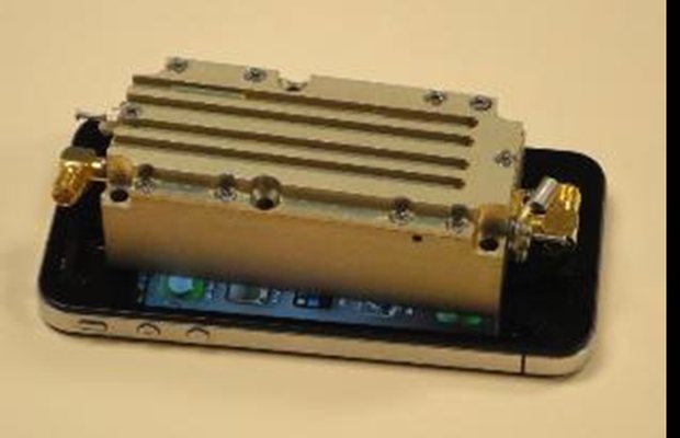
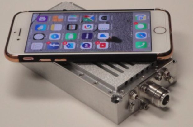
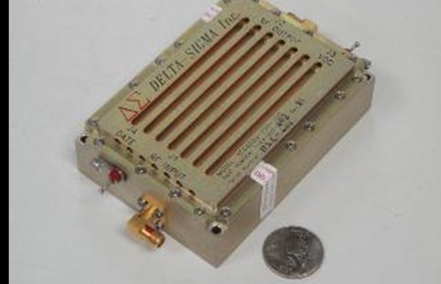
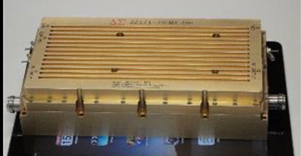
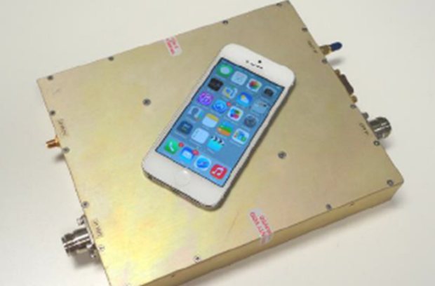
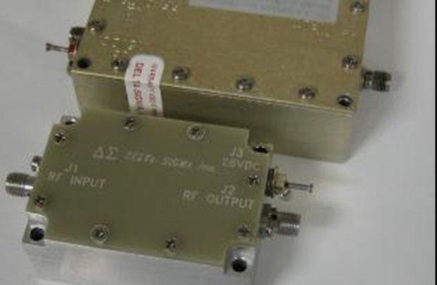
Production hardware, shown to scale. Aggregating to 8 kW CW in 4U.
Platform-agnostic across the band
Scalable solid-state modules that aggregate to multi-kilowatt output and slot into the transmit chain you already have. Any waveform or protocol in a single unit, with simultaneous multi-band operation and real-time switching.
Near perfect linearity
Input and output envelopes match to a negligible difference, so filters, pre-distortion and error correction leave the chain. Five-plus octaves in one unit, and any waveform a designer specifies is one the hardware carries.
Industry lowest phase noise
−110 dB at 0.1 Hz offset, 10 dB below the −100 dB at 1 Hz industry benchmark and held a decade closer to the carrier. A 100× improvement on the benchmark, and an order of magnitude past the best published figure.
Nanosecond RF bursts
Rise and fall times measured in nanoseconds, with zero droop and no ringing on the pulse. High-resolution pulse compression, fast time-of-arrival measurement, and pulse-shaping techniques that need a clean edge to work at all.
Nanosecond H/V switching
Horizontal to vertical switching on the nanosecond timescale, inside a single waveform. 3D waveforms, polarization-encoded data channels and polarimetric radar modes become available to designs that could never generate them.
Lowest SWaP, best density
CryoShield takes the heat out, so the same output fits a smaller envelope and modules chain inside the system to reach multi-kilowatt. Most power from the least footprint, and MTBF holds because the parts run cooler.
The claims, on instruments.
Linearity, pulse edges and polarization switching are the three things people ask us to prove first. These are the measurements we show them.


CryoShield™ cooling.
CryoShield is a non-toxic nanoparticle paste and powder. Put it directly on components, on housings, or use it as an additive in an immersion loop. No system redesign is required, so the thermal headroom shows up in hardware you have already built and already qualified.
How you spend that headroom is your call. Shrink the component, raise the output, ruggedize the part, or pack more of them into the same volume.
 FLIR · 53.1 °C with · 198 °C without
GPU overclocking figures are from synthetic testing. Dissipation in immersive cooling environments compounds beyond the air-cooled figure.
1.5× to 2.5× the power in 20–50% less rack.
The best-in-class competitor models used by SOCOM, BAE and Lockheed put 2 kW in an 8U chassis, 1 kW in 5U, and 500 W in 3U. The THEIA family covers all three of those points in 4U, and beats them on output at every one.
| Model | Frequency | Power | Size |
|---|---|---|---|
| THEIA-BVA | 30 – 520 MHz | 1 kW | 4U |
| THEIA-H | 1.5 – 30 MHz | 2 kW | 4U |
| THEIA-EV | 140 – 180 MHz | 2.5 kW | 4U |
 THEIA · 4U rack-mount
A kilowatt on the footprint of a phone, or eight of them in 4U.
The same amplification technology scales from a 2 W mini-format module to a 25 kW HF system. These are units in production.
A wide range of power and frequency.
One row per part, grouped by family and ordered from the highest output down. The bar spans the frequency it covers on a logarithmic scale, and the rated output is printed alongside it. Hover a row for the full spec.
Extensive catalog of deployed products.
Complete and modular amplifier products. The discrete RF building blocks inside them. And the combiners, filters and control units that orchestrate a full amplifier ecosystem. Items in production carry a COTS designation. Obsolete parts are not listed.
| Classification | Items | In development | What is in it | P/N families |
|---|---|---|---|---|
| Amplifier Sub-Systems | 135 | 2 | Assemblies, mainframes, plug-in modules, specialty systems | 2-60, 2-61, 2-62, 2-81 |
| Components | 282 | 0 | HF transformers, directional couplers, baluns, RF switches, PSU | 2-46, 2-27, 2-32, 2-17, 2-29 |
| Other Key Elements | 60 | 4 | Combiners and splitters, filter assemblies, logic and control | 2-47, 2-48, 2-65 |
JUPITER, QUASAR, PEGASUS, THEIA, CENTURION, HARRIER
Rack assemblies from 3U to 22U, pre-wired racks for rapid integration, and 64 plug-in modules from 1 W to 1.3 kW.
272 HF transformer assemblies alone
Impedance matching and signal coupling from 45 W to 3 kW, in 1:1, 4:1, 9:1 and 16:1 ratios, TMM dielectric and high-stability builds.
Combiners to 64-way, filters, logic
2-way through 64-way radial combiners to 16 kW p.e.p., bandpass and harmonic filters, RF switch matrices and control units.
A wide range of COTS solutions.
Although COTS parts are regularly used, we can also take that same proven technology and tailor it mechanically, environmentally, and electrically to a platform, a program, or an operating environment if needed.
Form factor
Chassis depth, rack-unit height, mounting patterns, connector locations, panel layouts and weight targets, to match an equipment bay you already have.
Hardening
MIL-STD-810 shock and vibration, MIL-STD-461 EMI/EMC, IP-rated enclosures, salt-fog and humidity, and temperature-range extension.
Cooling integration
CryoShield tuned to the host: air-cooled, liquid-cooled, immersion, or conductive cold-plate, with interfaces specified to your heat-rejection topology.
Connectors and I/O
RF, DC, control and data interfaces (38999, BNC, TNC, N, SMA, fiber, MIL-STD-1553, Ethernet variants) matched to your harnesses.
Conditioning
28 VDC, 115/230 VAC single or three-phase, 400 Hz and 800 Hz, inrush limiting, EMI filtering, and integrated conditioning to the platform.
Documentation and qualification
Test plans, FAT/SAT procedures, first-article inspection reports, MIL-STD qualification campaigns, and traceability for program acceptance.
CAGE 02XJ0 · ISO 9000 quality system compliant · ANSI/IPC-A-610 implemented · registered for U.S. Government contracting. DSI qualifies as both a small business and a nontraditional defense contractor. Products are dual use. Quality control policy, first-article inspection reports, test data and MIL-STD qualification evidence are available on request.
How can we help?
477 active components, three decades of fielded hardware, and amplification and thermal engineering that turns a hard requirement into capability nobody else can field. Bring us the problem the current chain cannot solve. Most of the time the answer is already on the shelf.
Contact Us